AIJ UWE
Validation data from the AIJ (Architectural Institute of Japan) benchmark cases—cleaned and packaged as an API.
Browse the cases Use the API Data paper (DOI) Cite
The cases
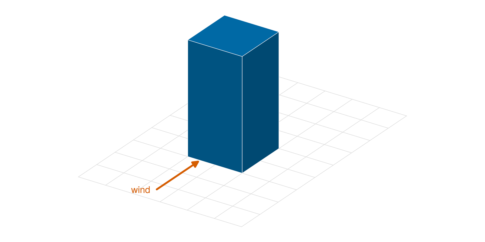 Case A — 1:1:2 building Isolated building · 186 points · \(U\), \(V\), \(W\) and \(k\) | 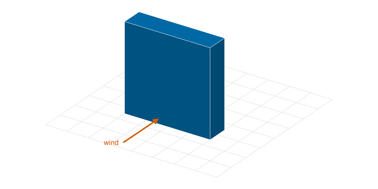 Case B — 1:4:4 slab Isolated slab · 224 points · \(U\), \(V\), \(W\) and \(k\) | 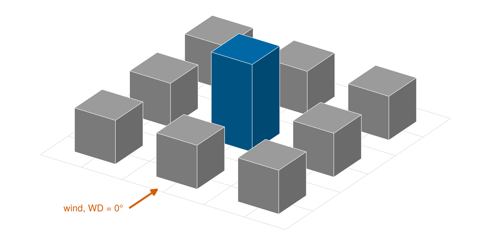 Case C — 3 × 3 block array Centre block at 0D, 1D or 2D (2D shown) · 1,080 scalar speeds at pedestrian height, 3 wind directions |
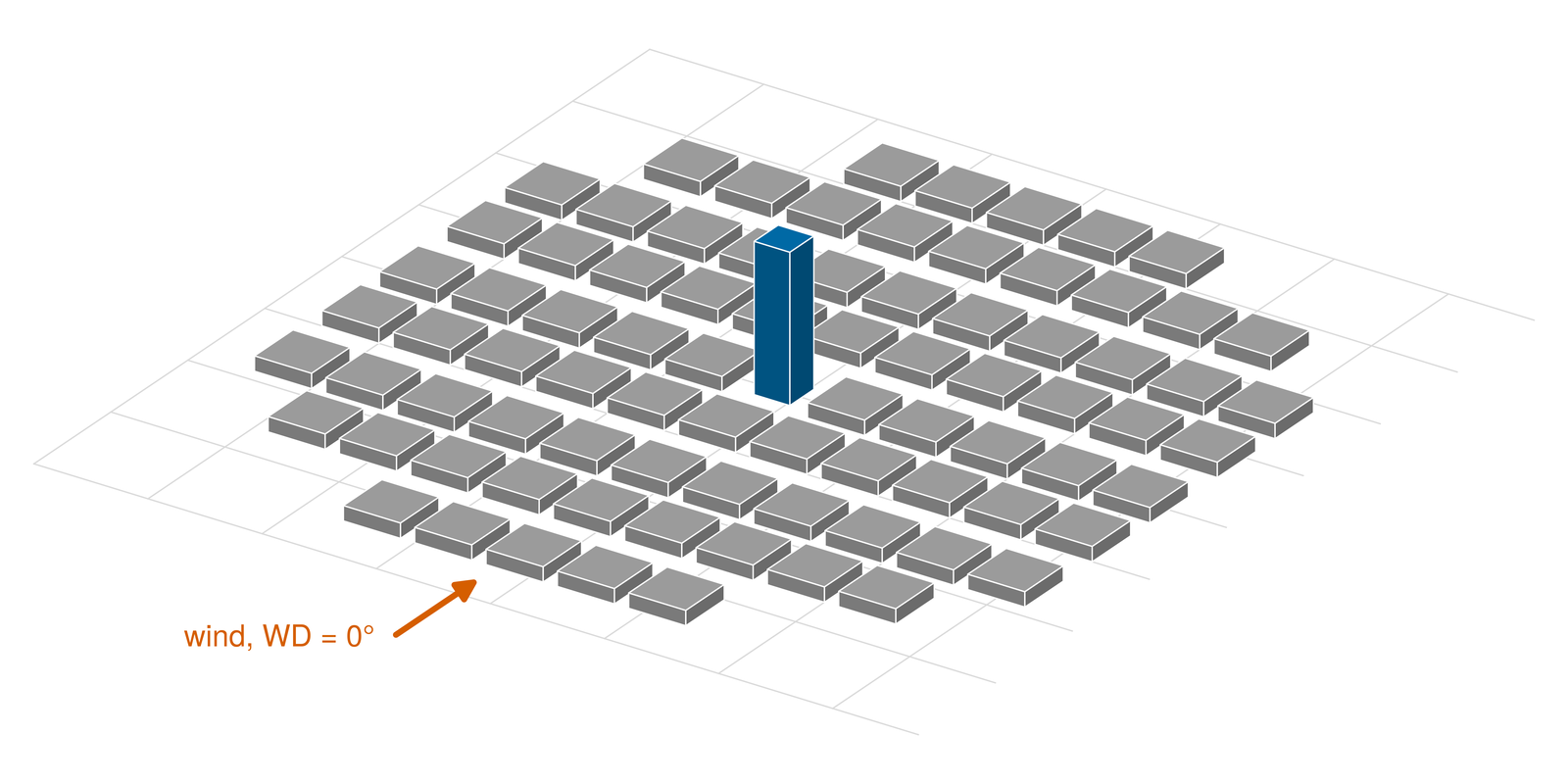 Case D — high-rise among city blocks A tower among 82 low blocks · 267 measurements: scalar speed at 3 wind directions, velocity at 33 points | 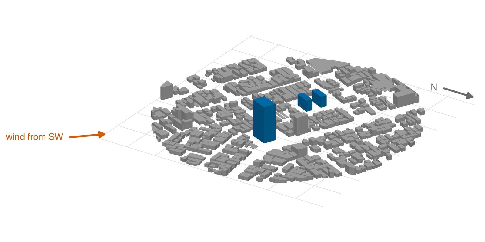 Case E — Niigata district Before and after a 60 m high-rise (after shown) · 2,560 velocity ratios over 16 wind directions | 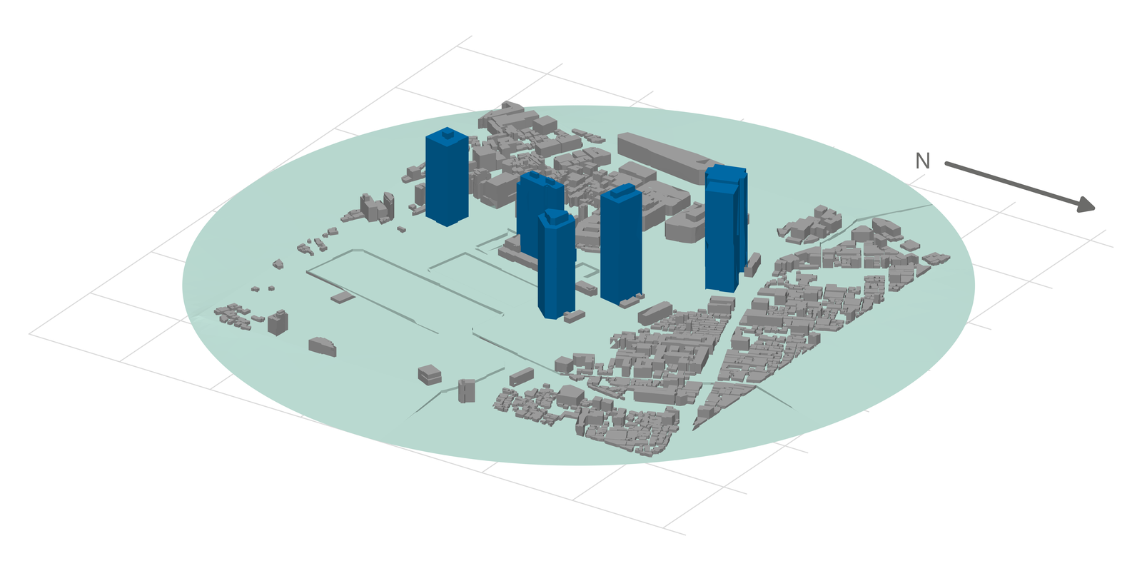 Case F — Shinjuku district Shinjuku sub-centre, Tokyo, November 1978: 1:800 tunnel (thermistor, 5 / 9 / 20 m) and a year of field cup anemometers; velocity ratio to the 500 m wind, 12 tunnel and 16 field directions. · 472 rows |
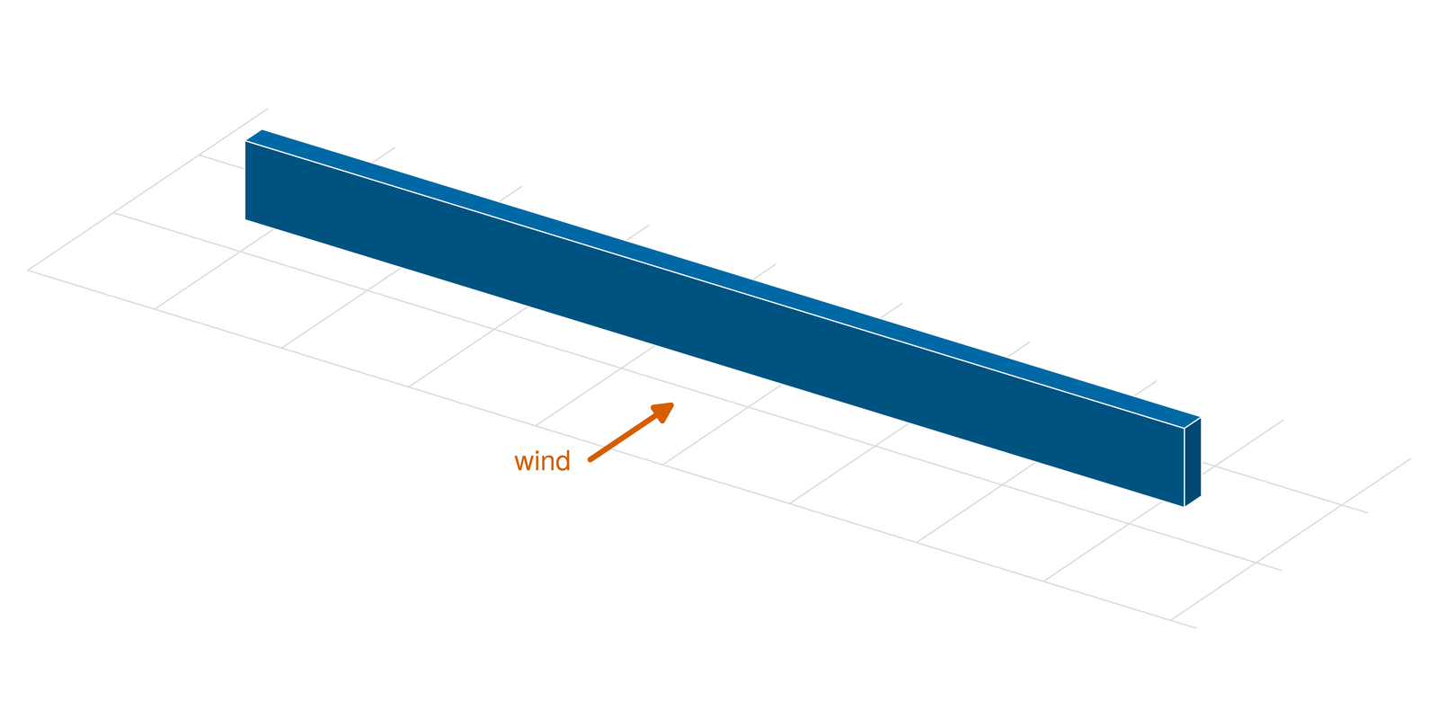 Case G — flow behind a tree belt Field observation behind the Tsuiji-matsu tree belt (a porous windbreak, 74 m × 2 m × 7 m with a 1.2 m gap below): normalised mean speed and \(k\) at 28 points on the centre section (sonic anemometers). · 28 rows | 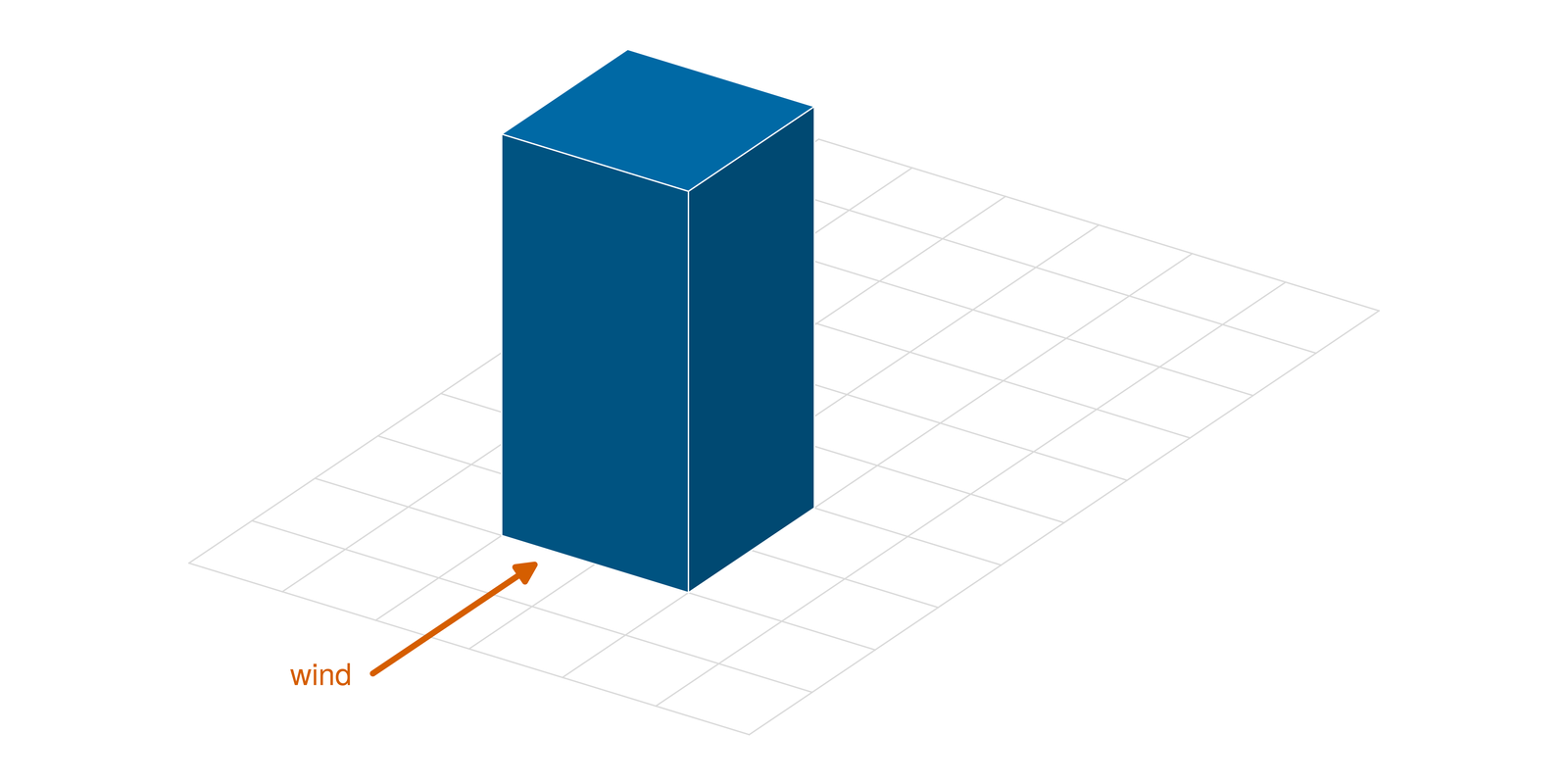 Case H — 1:1:2 building with a floor point source Isolated 1:1:2 building with an ethylene point source on the floor behind it: velocity (split-fibre hot wire) and concentration (hydrocarbon analyser) at 876 points. · 1,652 rows | 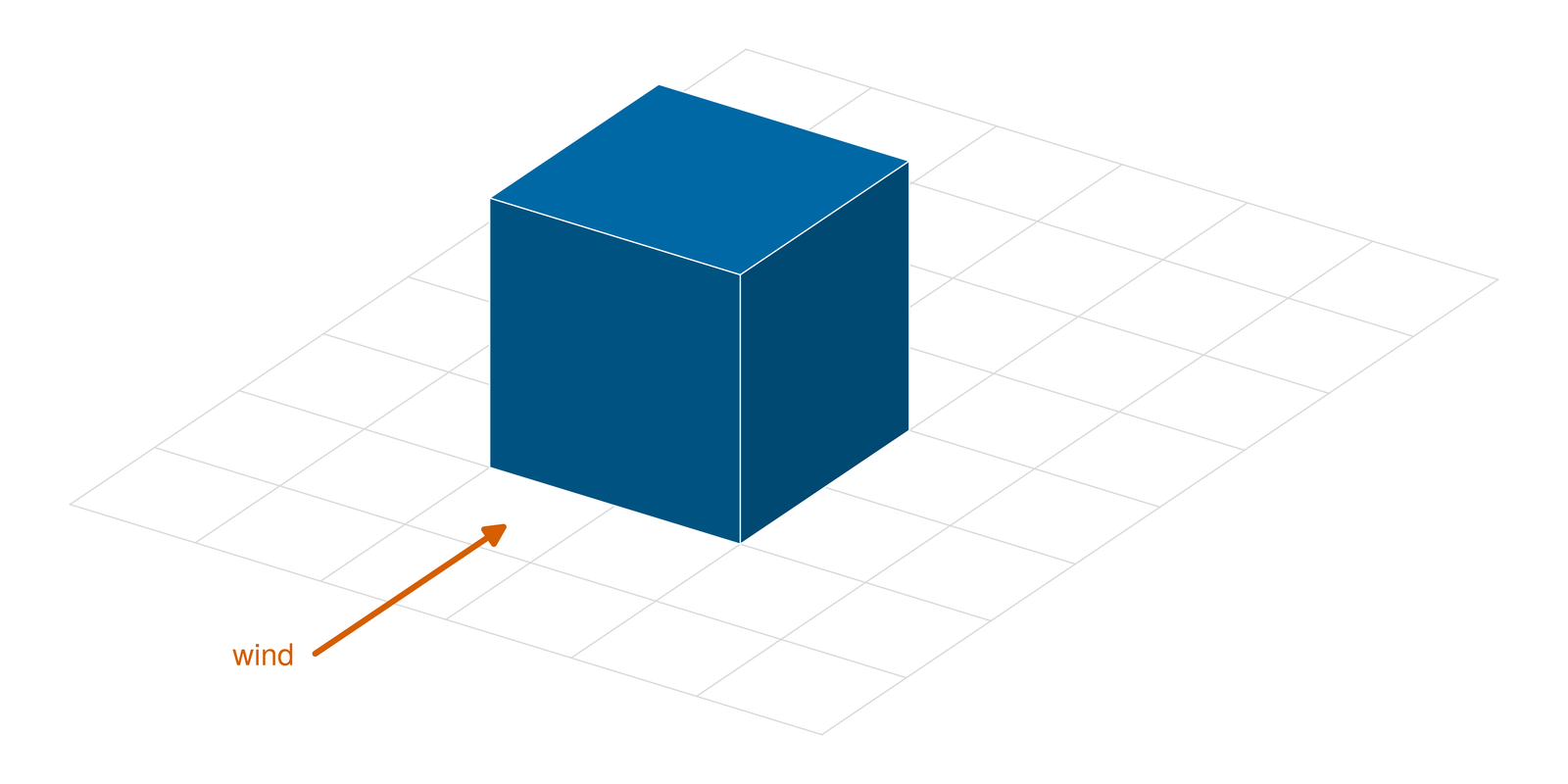 Case I — cube with a roof point source Isolated cube with an ethane point source at the centre of its roof: velocity (laser Doppler, 91 points) and concentration (hydrocarbon analyser, 539 points). · 630 rows |
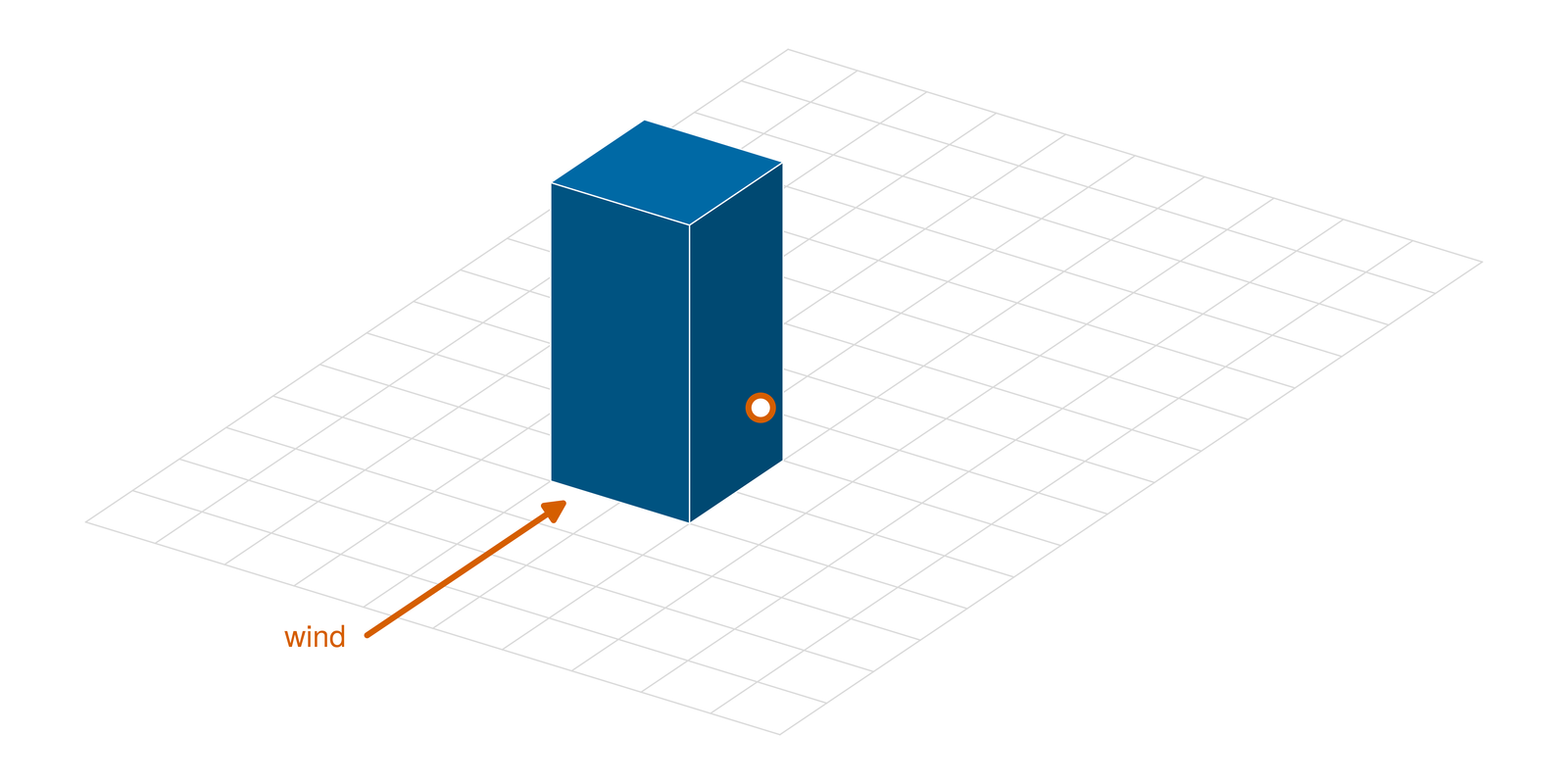 Case J — 1:1:2 building, non-isothermal Isolated 1:1:2 building with a floor tracer source in an unstably stratified boundary layer: velocity, temperature, tracer concentration and their turbulent fluxes at 444 points on three planes. · 444 rows | 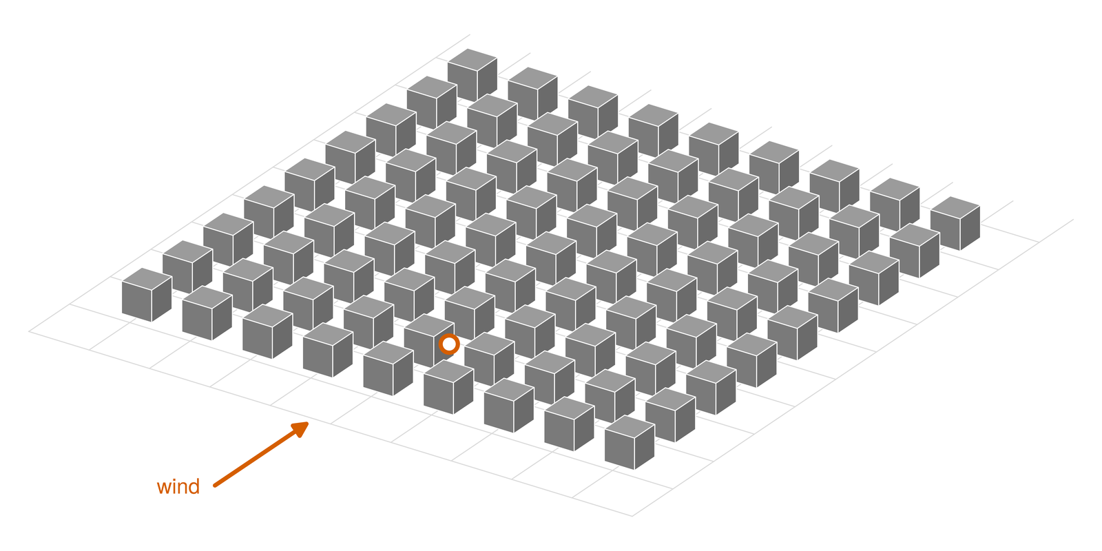 Case K — 9 x 9 cube array, point source 9 x 9 array of 0.06 m cubes with a tracer point source on the floor between rows 2 and 3: velocity and tracer concentration at 203 points in the streets and over the first rows. · 203 rows | 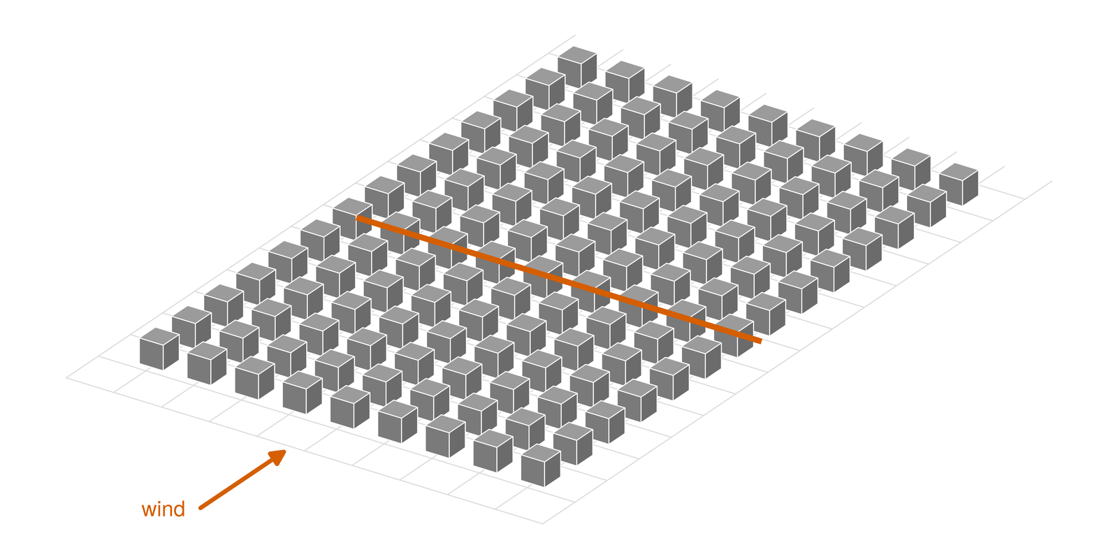 Case L — 9 x 14 cube array, line source, non-isothermal 14 rows by 9 columns of 0.06 m cubes with a tracer line source on the floor across the tunnel, in an unstably stratified boundary layer: velocity, temperature, concentration and their fluxes at 344 points in the streets and over the roofs. · 344 rows |
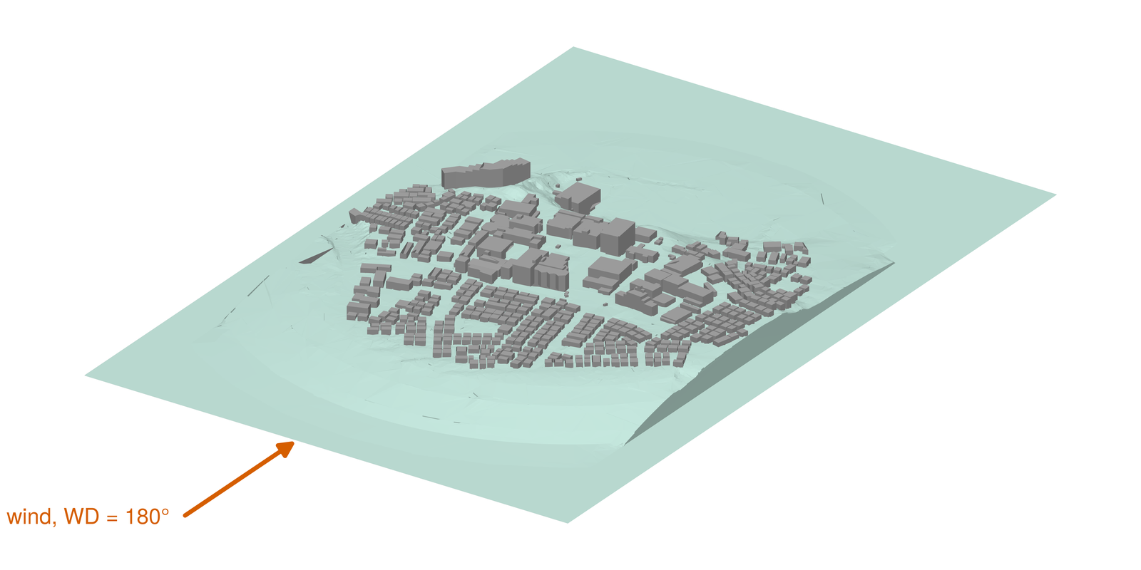 Case M — TPU Atsugi campus Tracer-gas release on the Tokyo Polytechnic University Atsugi campus: 1:600 tunnel (velocity at 180°, ethylene concentration at 175°, 180° and 185°) and 18 field runs with PMCH, 15 points 3 m above ground. · 330 rows |
Nomenclature: symbols, columns and scores
Geometry, reference scales and release
- \(H\), \(b\), \(D\) (m) — height of the building, cube, tower or tree belt; width of the building; edge of the cubes of Case C: the lengths the cases are drawn and normalised by
- \(U_H\) (m/s) — reference speed: the mean approach-flow speed at the height \(H\) (each Data page gives the value used)
- \(U_R\), \(H_R\), \(Z_R\) (m/s, m) — reference speed and height of a workbook: Case E, \(U_R\) at \(Z_R\) = 250 m full scale (1 m in the model); Case M, \(U_R\) and \(H_R\) at the reference point of the tunnel and of each field run
- \(U_{\mathrm{ref}}\), \(L_{\mathrm{ref}}\) (m/s, m) — reference speed and length of a case’s normalisation: \(U_H\) and \(H\) (\(U_R\) and \(H_R\) in Case M); for the velocity ratios the approach speed at 15.9 m (Case E) or at 500 m (Case F)
- \(U_b\) (m/s) — Case G: mean approach-flow speed at 9 m, the normalisation of its approach-flow table
- \(q\), \(c_{\mathrm{gas}}\) (m³/s, ppm) — tracer release of the experiment: volume flow of the released gas, and its tracer content (\(10^6\) ppm when pure); \(Q\) is the source strength given to a solve
- \(R_b\) (dimensionless) — bulk Richardson number of the heated-floor cases J and L (negative: unstable stratification)
- \(\mathrm{Re_H}\), \(\mathrm{Re_D}\) (dimensionless) — Reynolds numbers \(U_H H/\nu\) and \(U_H D/\nu\) (\(\nu\): kinematic viscosity of air)
- \(u_\ast\), \(z_0\), \(\kappa\) (m/s, mm, dimensionless) — friction velocity and roughness length of the log law fitted to the approach flow, and the von Kármán constant (0.41)
- \(\mathrm{WD}\) (column
wind_direction_deg; °) — wind direction (each frame says how it is counted); \(\mathrm{WD_R}\) is the mean direction of a field run at its reference point (Case M) - \(x\), \(y\), \(z\) (columns
x,y,z; m) — coordinates in the case’s frame (\(+x\), \(+y\) and \(+z\) are the positive directions; each Data page says which way \(+x\) points), \(z\) up from the floor of the tunnel or from the ground - \(\mathrm{d}x\) (m) — lattice spacing of the OpenLB and FluidX3D runs, in metres or as a fraction of \(H\) (\(H/64\))
- \(L_r\) (m) — reattachment length behind the building, read from a wake line at ground level; reported as \(L_r/H\)
Velocity and turbulence
- \(U\), \(V\), \(W\) (columns
U,V,W; m/s) — mean velocity along \(+x\), \(+y\), \(+z\); \(V\) is positive toward \(+y\) in every case - \(\lvert\mathbf{U}\rvert\) (m/s) — magnitude of the mean velocity vector, \(\sqrt{U^2+V^2+W^2}\)
- \(V_{\mathrm{s}}\) (column
Vs; m/s) — mean omnidirectional scalar speed of a thermistor (never a vector magnitude) - \(\overline{u'u'}\), \(\overline{v'v'}\), \(\overline{w'w'}\) (columns
uu,vv,ww; m²/s²) — velocity variances (overbar: time average, prime: fluctuation about it) - \(\overline{u'v'}\), \(\overline{u'w'}\), \(\overline{v'w'}\) (columns
uv,uw,vw; m²/s²) — Reynolds shear stresses - \(k = \tfrac{1}{2}\left(\overline{u'u'}+\overline{v'v'}+\overline{w'w'}\right)\) (column
k; m²/s²) — turbulent kinetic energy - \(U/U_{\mathrm{ref}}\) (column
velocity_ratio; dimensionless) — mean speed over the case’s reference speed (\(V_{\mathrm{s}}/U_{\mathrm{ref}}\) for a thermistor) - \(\sigma_{U/U_{\mathrm{ref}}}\) (column
velocity_ratio_sd; dimensionless) — standard deviation ofvelocity_ratioover the observations behind a field value (Case F) - \(k/U_{\mathrm{ref}}^2\) (column
k_ratio; dimensionless) — turbulent kinetic energy over the square of the reference speed, where only normalised values are published (Case G)
Concentration and temperature
- \(C\) (column
C; ppm) — mean tracer-gas concentration as published (volume fraction \(\times 10^6\) of the released gas diluted in air) - \(c_{\mathrm{rms}}\) (column
c_rms; ppm) — root mean square of the concentration fluctuation - \(c_0\) (ppm) — reference concentration, defined for each case on its Data page: \(c_0 = \dfrac{c_{\mathrm{gas}}\thinspace q}{U_H H^2}\) (\(U_R H_R^2\) in the denominator in Case M)
- \(c^\ast\) (column
concentration_ratio; dimensionless) — dimensionless concentration \(c^\ast = C/c_0\); the value of a solve is \(c\thinspace U_H H^2/Q\) for its mean concentration \(c\) and its source strength \(Q\) - \(\mathrm{Sc_t}\) (dimensionless) — turbulent Schmidt number of a solve (0.3, 0.5 and 0.7)
- \(T\), \(T_{\mathrm{rms}}\) (columns
T,T_rms; °C, K) — mean air temperature as published (Cases J and L) and the root mean square of its fluctuation - \(\overline{u'c'}\), \(\overline{v'c'}\), \(\overline{w'c'}\) (columns
uc,vc,wc; ppm·m/s) — turbulent concentration fluxes - \(\overline{u'\theta'}\), \(\overline{v'\theta'}\), \(\overline{w'\theta'}\) (columns
uT,vT,wT; K·m/s) — turbulent heat fluxes (\(\theta'\): the temperature fluctuation) - \(\theta = \dfrac{T_f - T}{T_f - T_H}\) (dimensionless) — floor-referenced temperature the solves of Cases J and L are scored on: 0 at the floor, 1 in the approach air at \(H\); \(T_f\) is the floor temperature and \(T_H\) the temperature of the approach flow at \(H\)
Scores
- \(n\) — number of pairs of a measured value \(o_i\) and a modelled value \(p_i\) at one point
- \(R\) — Pearson correlation coefficient of the pairs
- \(R^2\) — square of \(R\): share of the measured variance a linear fit to the model explains
- \(\mathrm{FAC2}\) — fraction of pairs with \(0.5 \le p_i/o_i \le 2\)
- \(\mathrm{FB}\) — fractional bias \(2(\overline{o}-\overline{p})/(\overline{o}+\overline{p})\), positive when the model is low
- \(\mathrm{HR}\) (hit rate) — fraction of pairs with \(\lvert p_i-o_i\rvert/\lvert o_i\rvert \le \delta_{\mathrm{rel}}\) or \(\lvert p_i-o_i\rvert \le \delta_{\mathrm{abs}}\), where \(\delta_{\mathrm{rel}} = 0.25\) and \(\delta_{\mathrm{abs}} = 0.05\thinspace U_H\) for a velocity component
- \(\mathrm{NMSE} = \dfrac{\overline{(o-p)^2}}{\overline{o}\thinspace \overline{p}}\) — normalised mean square error
- \(\mathrm{NAD} = \dfrac{\overline{\lvert o-p\rvert}}{\overline{o}+\overline{p}}\) — normalised absolute difference
- \(\mathrm{MG} = \exp\overline{(\ln o-\ln p)}\) — geometric mean bias
- \(\mathrm{VG} = \exp\overline{(\ln o-\ln p)^2}\) — geometric variance
- The ratio of \(\mathrm{FAC2}\) keeps its sign, so a model of the other sign than the measurement is a miss; \(\mathrm{FB}\), \(\mathrm{NMSE}\) and \(\mathrm{NAD}\) divide by the means, so they are undefined (shown as —) for a signed component unless the measured and the modelled mean are both positive
- VDI 3783-9 calls the hit rate \(q\) and the tolerances \(D\) and \(W\); on this site those letters keep their other meanings (\(q\) the tracer release rate, \(D\) the block size of Case C, \(W\) the vertical velocity)
- The detection limit of a concentration is one value per case, \(10^{-3}\) of the largest measured value. It sets \(\delta_{\mathrm{abs}}\) of the hit rate and the both-below rule of \(\mathrm{FAC2}\), and floors the values in \(\mathrm{MG}\) and \(\mathrm{VG}\).
- The scores \(\mathrm{FB}\), \(\mathrm{FAC2}\), \(\mathrm{NMSE}\), \(\mathrm{NAD}\), \(\mathrm{MG}\) and \(\mathrm{VG}\) follow Chang & Hanna (2004); the hit rate follows VDI 3783-9.
Quantities scored
- \(U\), \(V\) and \(W\) (mean velocity components) over \(U_H\)
- \(k\) (turbulent kinetic energy) over \(U_H^2\)
- the speed \(\lvert\mathbf{U}\rvert\) and \(\sqrt{\lvert\mathbf{U}\rvert^2+2k}\), against a thermistor’s \(V_{\mathrm{s}}\)
- \(c^\ast = C/c_0\) (dimensionless concentration) at turbulent Schmidt numbers \(\mathrm{Sc_t}\) of 0.3, 0.5 and 0.7
- \(\theta\) (floor-referenced temperature)
Cases at a glance
| Case | What it is | Measured | Validation |
|---|---|---|---|
| Case A | Isolated 1:1:2 building, velocity field (split-fibre hot wire). | 186 rows over 186 points; \(U\), \(V\), \(W\), \(\overline{u'u'}\), \(\overline{v'v'}\), \(\overline{w'w'}\), \(k\) | OpenFOAM 12, OpenLB, FluidX3D, ML surrogate |
| Case B | Isolated 1:4:4 slab, velocity field (split-fibre hot wire). | 224 rows over 224 points; \(U\), \(V\), \(W\), \(\overline{u'u'}\), \(\overline{v'v'}\), \(\overline{w'w'}\), \(k\) | OpenFOAM 12, OpenLB, FluidX3D, ML surrogate |
| Case C | 3 x 3 array of 0.20 m cubes, centre block at 0D / 1D / 2D, pedestrian-height scalar speed (thermistor), 3 wind directions. | 1,080 rows over 120 points; \(V_{\mathrm{s}}\) | OpenFOAM 12, ML surrogate |
| Case D | 1:1:4 tower in a regular array of 82 low blocks, pedestrian-height scalar speed (thermistor, 3 wind directions) plus a 33-point split-fibre velocity field at \(\mathrm{WD} = 0\). | 267 rows over 78 points; \(V_{\mathrm{s}}\), \(U\), \(V\), \(W\), \(\overline{u'u'}\), \(\overline{v'v'}\), \(\overline{w'w'}\), \(k\) | OpenFOAM 12, ML surrogate |
| Case E | Real district in Niigata at 1:250, before and after a 60 m high-rise and two 18 m mid-rises; pedestrian-height velocity ratio (thermistor), 16 wind directions. | 2,560 rows over 80 points; \(U/U_{\mathrm{ref}}\) | OpenFOAM 12, ML surrogate |
| Case F | Shinjuku sub-centre, Tokyo, November 1978: 1:800 tunnel (thermistor, 5 / 9 / 20 m) and a year of field cup anemometers; velocity ratio to the 500 m wind, 12 tunnel and 16 field directions. | 472 rows over 13 points; \(U/U_{\mathrm{ref}}\), \(\sigma_{U/U_{\mathrm{ref}}}\) | OpenFOAM 12 |
| Case G | Field observation behind the Tsuiji-matsu tree belt (a porous windbreak, 74 m × 2 m × 7 m with a 1.2 m gap below): normalised mean speed and \(k\) at 28 points on the centre section (sonic anemometers). | 28 rows over 28 points; \(U/U_{\mathrm{ref}}\), \(k/U_{\mathrm{ref}}^2\) | OpenFOAM 12 |
| Case H | Isolated 1:1:2 building with an ethylene point source on the floor behind it: velocity (split-fibre hot wire) and concentration (hydrocarbon analyser) at 876 points. | 1,652 rows over 876 points; \(U\), \(V\), \(W\), \(\overline{u'u'}\), \(\overline{v'v'}\), \(\overline{w'w'}\), \(k\), \(C\), \(c_{\mathrm{rms}}\), \(c^\ast\) | OpenFOAM 12 |
| Case I | Isolated cube with an ethane point source at the centre of its roof: velocity (laser Doppler, 91 points) and concentration (hydrocarbon analyser, 539 points). | 630 rows over 630 points; \(U\), \(V\), \(W\), \(k\), \(C\), \(c^\ast\) | OpenFOAM 12, OpenFOAM 12 k-ε, OpenFOAM 12 k-ω SST |
| Case J | Isolated 1:1:2 building with a floor tracer source in an unstably stratified boundary layer: velocity, temperature, tracer concentration and their turbulent fluxes at 444 points on three planes. | 444 rows over 444 points; \(U\), \(V\), \(W\), \(\overline{u'u'}\), \(\overline{v'v'}\), \(\overline{w'w'}\), \(k\), \(C\), \(c_{\mathrm{rms}}\), \(c^\ast\), \(T\), \(T_{\mathrm{rms}}\), \(\overline{u'\theta'}\), \(\overline{v'\theta'}\), \(\overline{w'\theta'}\) | OpenFOAM 12 (UMF), OpenFOAM 12 (UMF) buoyantKEpsilon |
| Case K | 9 x 9 array of 0.06 m cubes with a tracer point source on the floor between rows 2 and 3: velocity and tracer concentration at 203 points in the streets and over the first rows. | 203 rows over 203 points; \(U\), \(V\), \(W\), \(\overline{u'u'}\), \(\overline{v'v'}\), \(\overline{w'w'}\), \(k\), \(C\), \(c_{\mathrm{rms}}\), \(c^\ast\) | OpenFOAM 12 |
| Case L | 14 rows by 9 columns of 0.06 m cubes with a tracer line source on the floor across the tunnel, in an unstably stratified boundary layer: velocity, temperature, concentration and their fluxes at 344 points in the streets and over the roofs. | 344 rows over 344 points; \(U\), \(V\), \(W\), \(\overline{u'u'}\), \(\overline{v'v'}\), \(\overline{w'w'}\), \(k\), \(\overline{u'v'}\), \(\overline{u'w'}\), \(C\), \(c_{\mathrm{rms}}\), \(c^\ast\), \(T\), \(T_{\mathrm{rms}}\), \(\overline{u'c'}\), \(\overline{v'c'}\), \(\overline{w'c'}\), \(\overline{u'\theta'}\), \(\overline{v'\theta'}\), \(\overline{w'\theta'}\) | OpenFOAM 12 (UMF) |
| Case M | Tracer-gas release on the Tokyo Polytechnic University Atsugi campus: 1:600 tunnel (velocity at 180°, ethylene concentration at 175°, 180° and 185°) and 18 field runs with PMCH, 15 points 3 m above ground. | 330 rows over 15 points; \(U\), \(V\), \(W\), \(\overline{u'u'}\), \(\overline{v'v'}\), \(\overline{w'w'}\), \(k\), \(C\), \(c_{\mathrm{rms}}\), \(c^\ast\) | OpenFOAM 12 |
Nomenclature: symbols, columns and scores
Geometry, reference scales and release
- \(H\), \(b\), \(D\) (m) — height of the building, cube, tower or tree belt; width of the building; edge of the cubes of Case C: the lengths the cases are drawn and normalised by
- \(U_H\) (m/s) — reference speed: the mean approach-flow speed at the height \(H\) (each Data page gives the value used)
- \(U_R\), \(H_R\), \(Z_R\) (m/s, m) — reference speed and height of a workbook: Case E, \(U_R\) at \(Z_R\) = 250 m full scale (1 m in the model); Case M, \(U_R\) and \(H_R\) at the reference point of the tunnel and of each field run
- \(U_{\mathrm{ref}}\), \(L_{\mathrm{ref}}\) (m/s, m) — reference speed and length of a case’s normalisation: \(U_H\) and \(H\) (\(U_R\) and \(H_R\) in Case M); for the velocity ratios the approach speed at 15.9 m (Case E) or at 500 m (Case F)
- \(U_b\) (m/s) — Case G: mean approach-flow speed at 9 m, the normalisation of its approach-flow table
- \(q\), \(c_{\mathrm{gas}}\) (m³/s, ppm) — tracer release of the experiment: volume flow of the released gas, and its tracer content (\(10^6\) ppm when pure); \(Q\) is the source strength given to a solve
- \(R_b\) (dimensionless) — bulk Richardson number of the heated-floor cases J and L (negative: unstable stratification)
- \(\mathrm{Re_H}\), \(\mathrm{Re_D}\) (dimensionless) — Reynolds numbers \(U_H H/\nu\) and \(U_H D/\nu\) (\(\nu\): kinematic viscosity of air)
- \(u_\ast\), \(z_0\), \(\kappa\) (m/s, mm, dimensionless) — friction velocity and roughness length of the log law fitted to the approach flow, and the von Kármán constant (0.41)
- \(\mathrm{WD}\) (column
wind_direction_deg; °) — wind direction (each frame says how it is counted); \(\mathrm{WD_R}\) is the mean direction of a field run at its reference point (Case M) - \(x\), \(y\), \(z\) (columns
x,y,z; m) — coordinates in the case’s frame (\(+x\), \(+y\) and \(+z\) are the positive directions; each Data page says which way \(+x\) points), \(z\) up from the floor of the tunnel or from the ground - \(\mathrm{d}x\) (m) — lattice spacing of the OpenLB and FluidX3D runs, in metres or as a fraction of \(H\) (\(H/64\))
- \(L_r\) (m) — reattachment length behind the building, read from a wake line at ground level; reported as \(L_r/H\)
Velocity and turbulence
- \(U\), \(V\), \(W\) (columns
U,V,W; m/s) — mean velocity along \(+x\), \(+y\), \(+z\); \(V\) is positive toward \(+y\) in every case - \(\lvert\mathbf{U}\rvert\) (m/s) — magnitude of the mean velocity vector, \(\sqrt{U^2+V^2+W^2}\)
- \(V_{\mathrm{s}}\) (column
Vs; m/s) — mean omnidirectional scalar speed of a thermistor (never a vector magnitude) - \(\overline{u'u'}\), \(\overline{v'v'}\), \(\overline{w'w'}\) (columns
uu,vv,ww; m²/s²) — velocity variances (overbar: time average, prime: fluctuation about it) - \(\overline{u'v'}\), \(\overline{u'w'}\), \(\overline{v'w'}\) (columns
uv,uw,vw; m²/s²) — Reynolds shear stresses - \(k = \tfrac{1}{2}\left(\overline{u'u'}+\overline{v'v'}+\overline{w'w'}\right)\) (column
k; m²/s²) — turbulent kinetic energy - \(U/U_{\mathrm{ref}}\) (column
velocity_ratio; dimensionless) — mean speed over the case’s reference speed (\(V_{\mathrm{s}}/U_{\mathrm{ref}}\) for a thermistor) - \(\sigma_{U/U_{\mathrm{ref}}}\) (column
velocity_ratio_sd; dimensionless) — standard deviation ofvelocity_ratioover the observations behind a field value (Case F) - \(k/U_{\mathrm{ref}}^2\) (column
k_ratio; dimensionless) — turbulent kinetic energy over the square of the reference speed, where only normalised values are published (Case G)
Concentration and temperature
- \(C\) (column
C; ppm) — mean tracer-gas concentration as published (volume fraction \(\times 10^6\) of the released gas diluted in air) - \(c_{\mathrm{rms}}\) (column
c_rms; ppm) — root mean square of the concentration fluctuation - \(c_0\) (ppm) — reference concentration, defined for each case on its Data page: \(c_0 = \dfrac{c_{\mathrm{gas}}\thinspace q}{U_H H^2}\) (\(U_R H_R^2\) in the denominator in Case M)
- \(c^\ast\) (column
concentration_ratio; dimensionless) — dimensionless concentration \(c^\ast = C/c_0\); the value of a solve is \(c\thinspace U_H H^2/Q\) for its mean concentration \(c\) and its source strength \(Q\) - \(\mathrm{Sc_t}\) (dimensionless) — turbulent Schmidt number of a solve (0.3, 0.5 and 0.7)
- \(T\), \(T_{\mathrm{rms}}\) (columns
T,T_rms; °C, K) — mean air temperature as published (Cases J and L) and the root mean square of its fluctuation - \(\overline{u'c'}\), \(\overline{v'c'}\), \(\overline{w'c'}\) (columns
uc,vc,wc; ppm·m/s) — turbulent concentration fluxes - \(\overline{u'\theta'}\), \(\overline{v'\theta'}\), \(\overline{w'\theta'}\) (columns
uT,vT,wT; K·m/s) — turbulent heat fluxes (\(\theta'\): the temperature fluctuation) - \(\theta = \dfrac{T_f - T}{T_f - T_H}\) (dimensionless) — floor-referenced temperature the solves of Cases J and L are scored on: 0 at the floor, 1 in the approach air at \(H\); \(T_f\) is the floor temperature and \(T_H\) the temperature of the approach flow at \(H\)
Scores
- \(n\) — number of pairs of a measured value \(o_i\) and a modelled value \(p_i\) at one point
- \(R\) — Pearson correlation coefficient of the pairs
- \(R^2\) — square of \(R\): share of the measured variance a linear fit to the model explains
- \(\mathrm{FAC2}\) — fraction of pairs with \(0.5 \le p_i/o_i \le 2\)
- \(\mathrm{FB}\) — fractional bias \(2(\overline{o}-\overline{p})/(\overline{o}+\overline{p})\), positive when the model is low
- \(\mathrm{HR}\) (hit rate) — fraction of pairs with \(\lvert p_i-o_i\rvert/\lvert o_i\rvert \le \delta_{\mathrm{rel}}\) or \(\lvert p_i-o_i\rvert \le \delta_{\mathrm{abs}}\), where \(\delta_{\mathrm{rel}} = 0.25\) and \(\delta_{\mathrm{abs}} = 0.05\thinspace U_H\) for a velocity component
- \(\mathrm{NMSE} = \dfrac{\overline{(o-p)^2}}{\overline{o}\thinspace \overline{p}}\) — normalised mean square error
- \(\mathrm{NAD} = \dfrac{\overline{\lvert o-p\rvert}}{\overline{o}+\overline{p}}\) — normalised absolute difference
- \(\mathrm{MG} = \exp\overline{(\ln o-\ln p)}\) — geometric mean bias
- \(\mathrm{VG} = \exp\overline{(\ln o-\ln p)^2}\) — geometric variance
- The ratio of \(\mathrm{FAC2}\) keeps its sign, so a model of the other sign than the measurement is a miss; \(\mathrm{FB}\), \(\mathrm{NMSE}\) and \(\mathrm{NAD}\) divide by the means, so they are undefined (shown as —) for a signed component unless the measured and the modelled mean are both positive
- VDI 3783-9 calls the hit rate \(q\) and the tolerances \(D\) and \(W\); on this site those letters keep their other meanings (\(q\) the tracer release rate, \(D\) the block size of Case C, \(W\) the vertical velocity)
- The detection limit of a concentration is one value per case, \(10^{-3}\) of the largest measured value. It sets \(\delta_{\mathrm{abs}}\) of the hit rate and the both-below rule of \(\mathrm{FAC2}\), and floors the values in \(\mathrm{MG}\) and \(\mathrm{VG}\).
- The scores \(\mathrm{FB}\), \(\mathrm{FAC2}\), \(\mathrm{NMSE}\), \(\mathrm{NAD}\), \(\mathrm{MG}\) and \(\mathrm{VG}\) follow Chang & Hanna (2004); the hit rate follows VDI 3783-9.
Quantities scored
- \(U\), \(V\) and \(W\) (mean velocity components) over \(U_H\)
- \(k\) (turbulent kinetic energy) over \(U_H^2\)
- the speed \(\lvert\mathbf{U}\rvert\) and \(\sqrt{\lvert\mathbf{U}\rvert^2+2k}\), against a thermistor’s \(V_{\mathrm{s}}\)
- \(c^\ast = C/c_0\) (dimensionless concentration) at turbulent Schmidt numbers \(\mathrm{Sc_t}\) of 0.3, 0.5 and 0.7
- \(\theta\) (floor-referenced temperature)
Where to go
- Cases: a page per case with its render, status and key numbers, then its reference data and its validation.
- Validation: every case against every engine in one table, and the method.
- Known data issues: units, signs, frames and scalar vs vector speed, per case.
- API: every endpoint with
curland Python examples, and the walk for agents. - About and cite: the citations of the API, the data paper and each case, the licence, and how a release is reproduced.
Data: Kikumoto et al. (2026), CC BY 4.0. Collectors per case on each Data page.